5. Virpil ACE Pedal FFB Mod by Number481
5.1 Introduction
Welcome to the documentation for the Virpil ACE Pedal Force-Feedback (FFB) Mod, a DIY project designed by community member Number481. This guide provides the information you need to add force feedback to your Virpil ACE rudder pedals using a VPforce motor kit and 3D-printed parts.
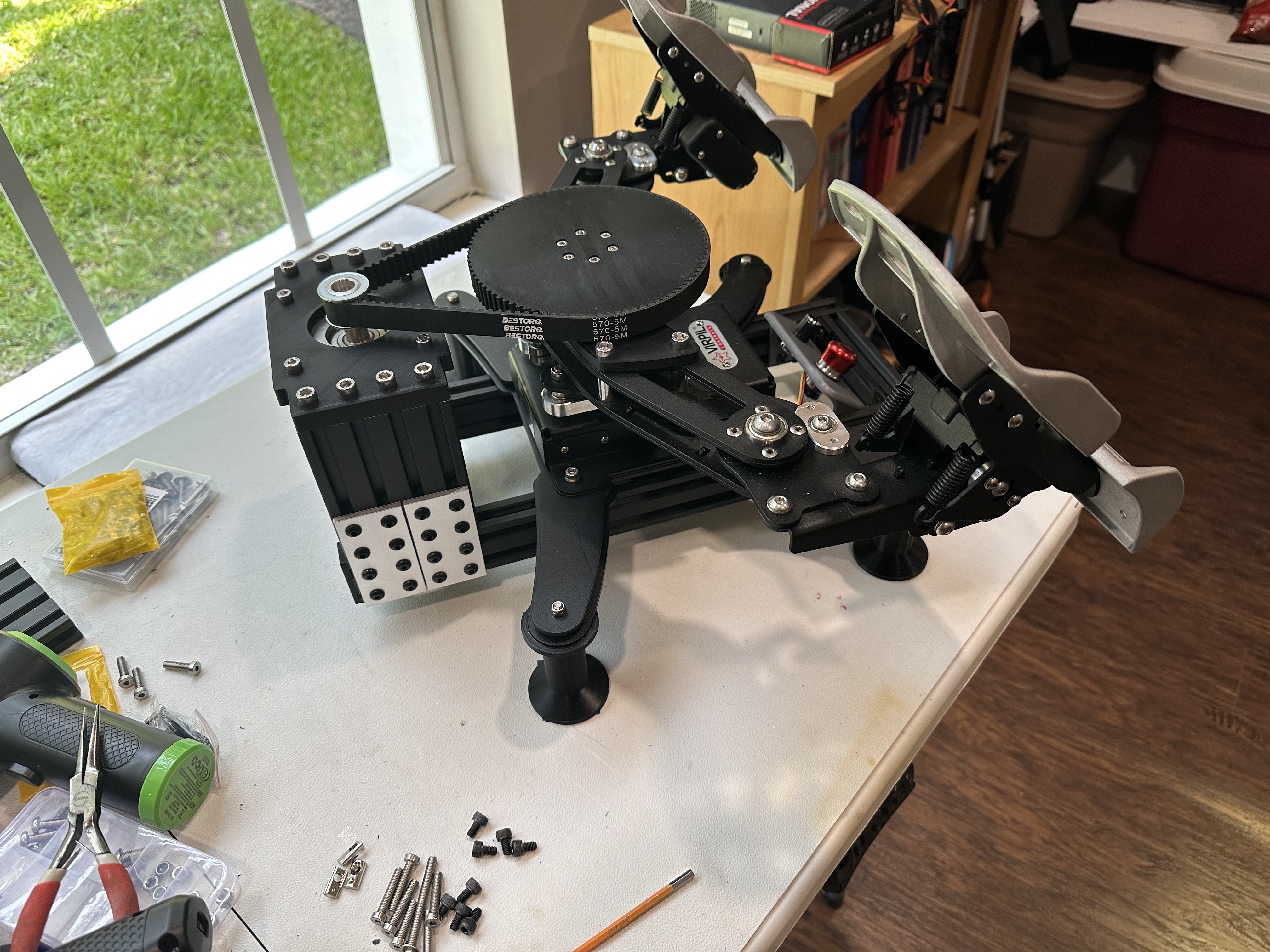
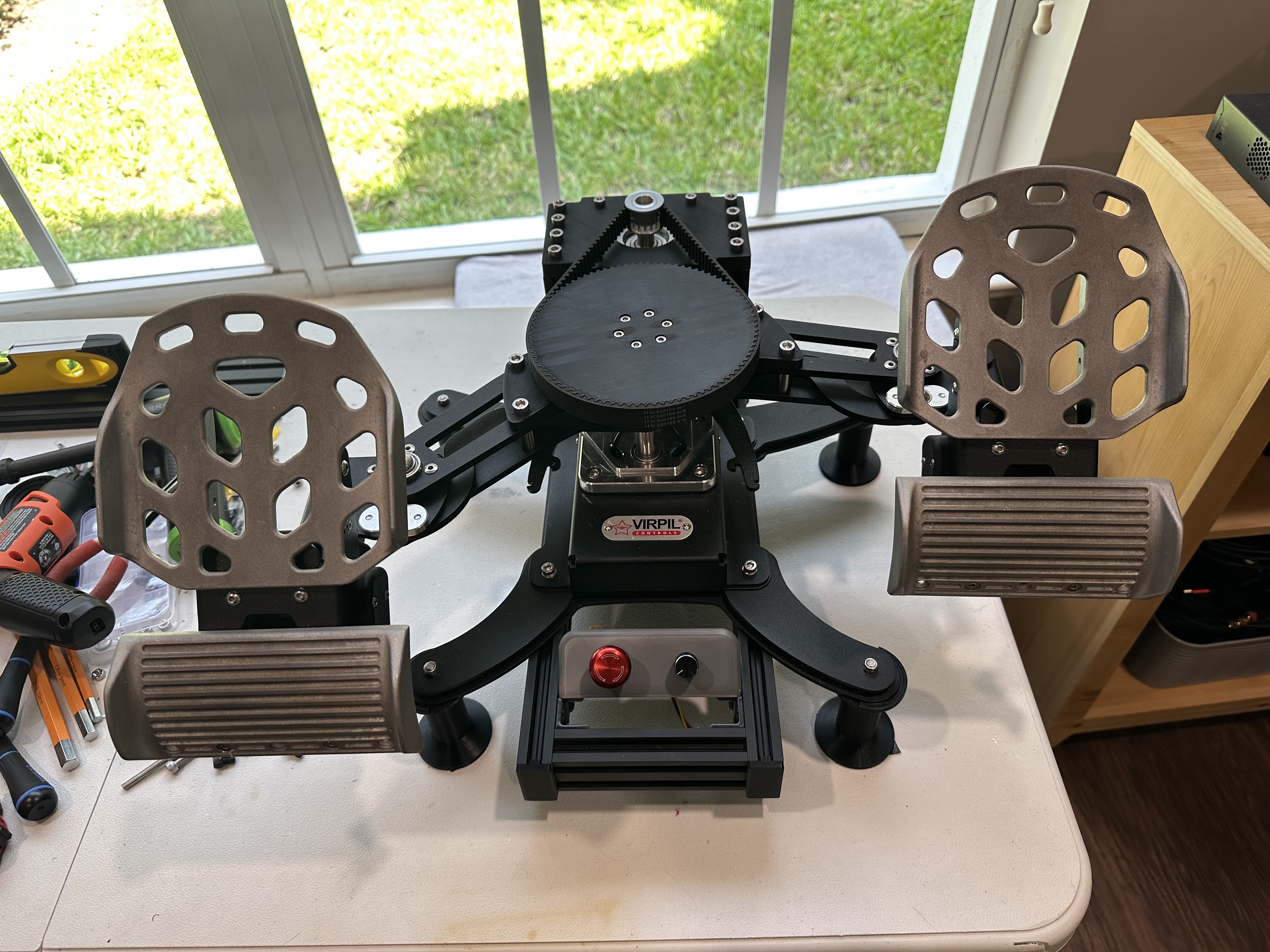
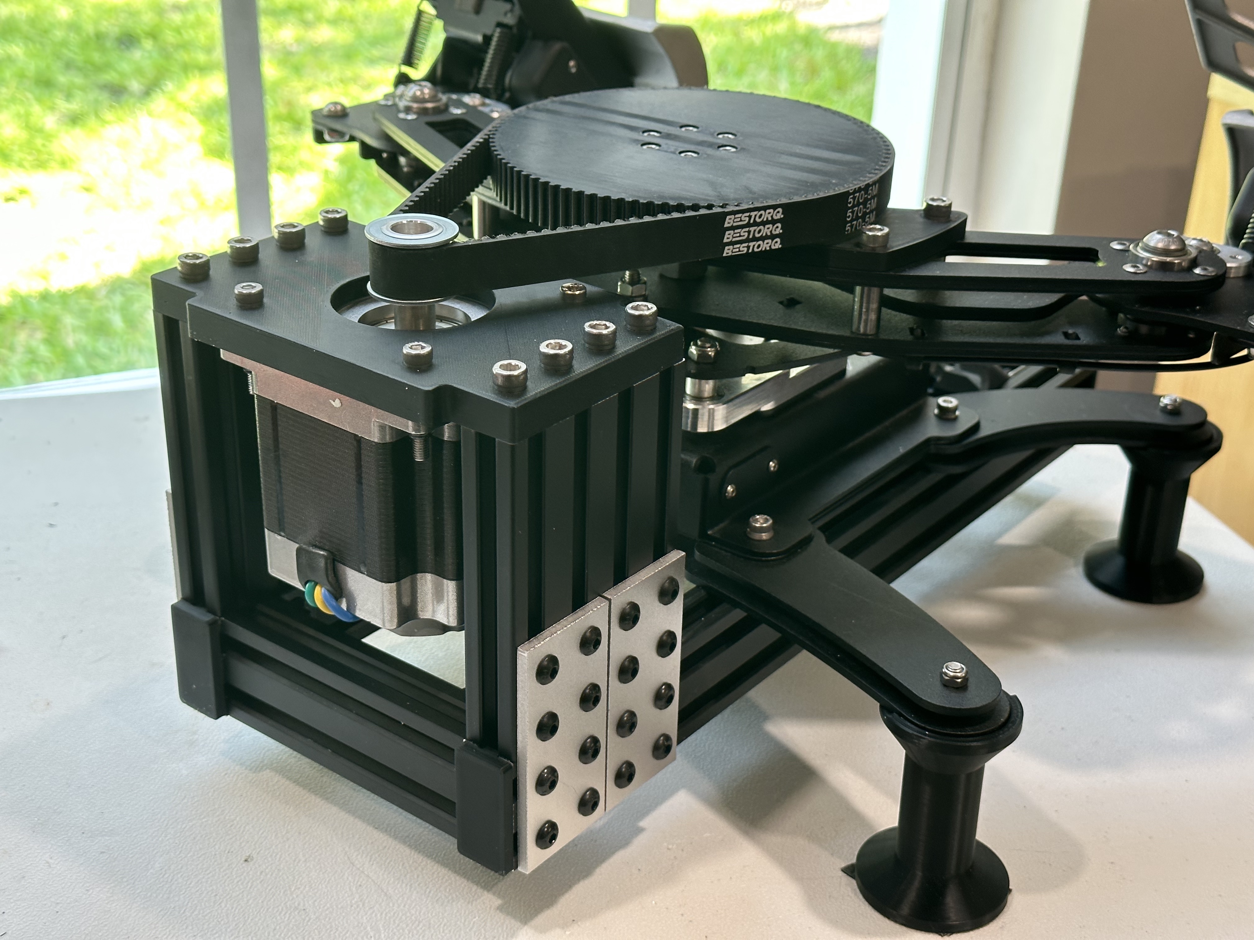
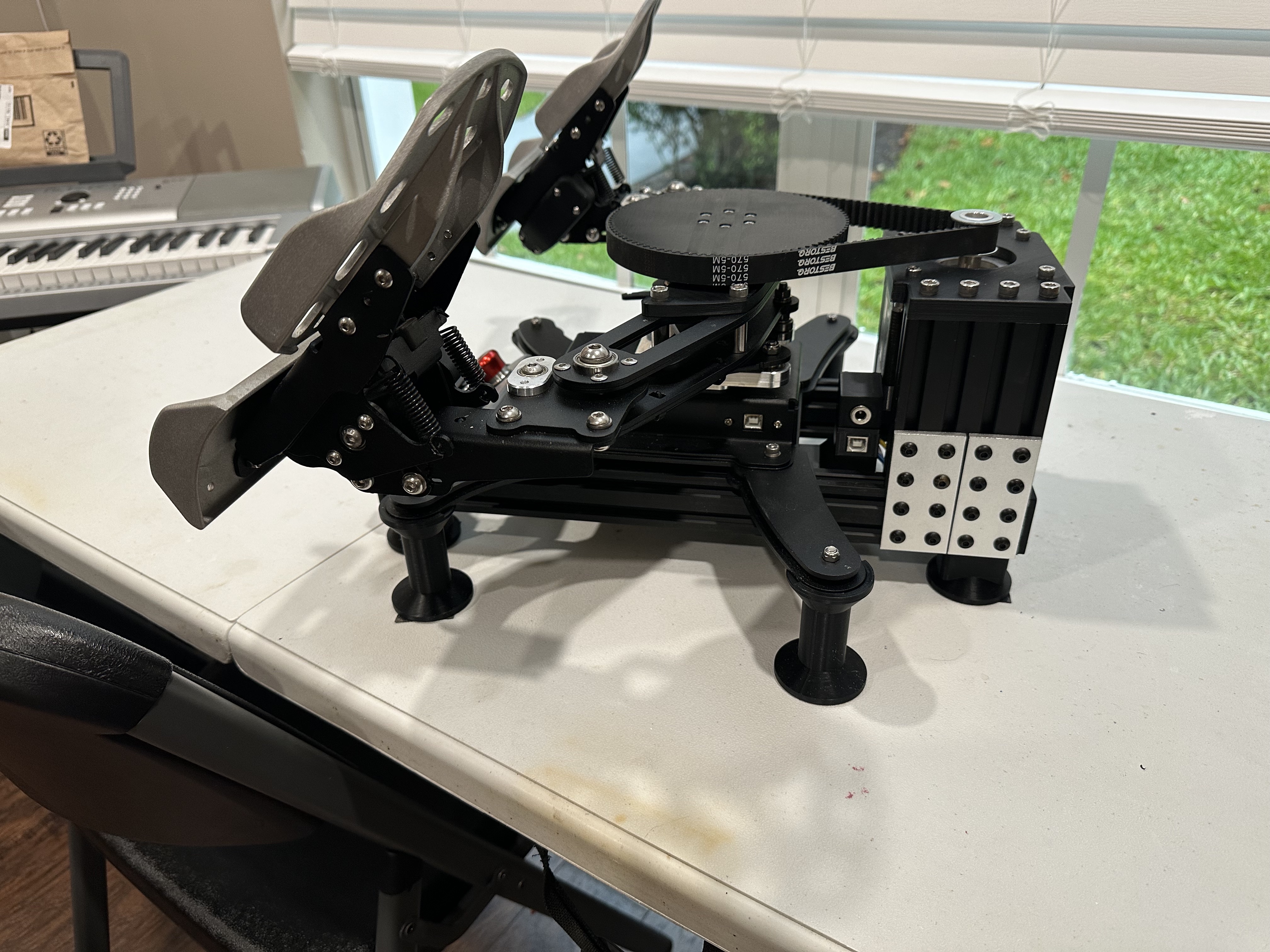
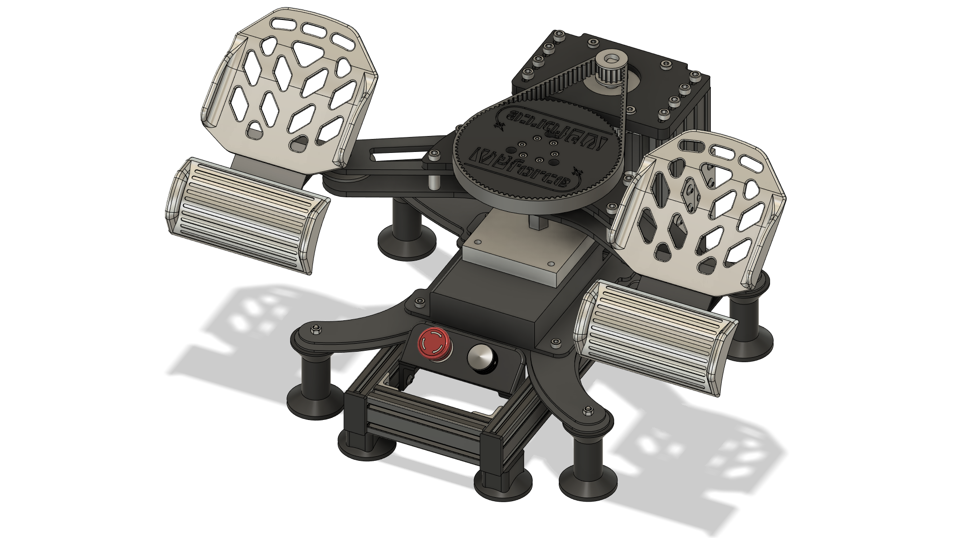
The mod uses a belt-driven 6:1 gear ratio (15-tooth drive pulley and 90-tooth main pulley) with the 86BLF-03 motor kit. The design requires no permanent modifications to the pedals — no drilling of pedal arms — and is fully reversible.
Note
This page is compiled from the original project documentation provided by Number481 on GitHub. All credit for the design and development of this mod goes to them.
5.1.1 Key Features
- Fully Reversible: No drilling or permanent modifications required to the pedal arms.
- High-Fidelity Force Feedback: Adds dynamic effects such as spring force, friction, damping, and vibrations to your pedals.
- Strong Performance: Achieves greater resistance than stock pedals with the heaviest springs.
- 6:1 Gear Ratio: Belt-driven system using a 15-tooth drive pulley and 90-tooth main pulley.
- Throw Limiters : Optional to maintain similar throw to stock pedals.
- Aluminum Extrusion Frame: Rigid, adjustable frame built from T-slot aluminum extrusion.
5.2 Prerequisites
Before you begin, you will need the following:
- Virpil ACE rudder pedals
- VPforce 86BLF-03 single motor kit
- A 3D printer capable of printing all required STL files
- All required hardware as specified in the Bill of Materials
Proceed at Your Own Risk
Modify your pedals at your own risk. Long-term effects of lateral bearing forces on the pedal mechanism are not fully characterized.
5.3 Project Resources
All files for this project are hosted on GitHub:
Number481/VirpilACE-VPForce-Mod on GitHub
The repository includes:
- STLs/ — 3D printable components
- STEP/ — Full 3D assembly files for CAD reference
- Photos/ — Build documentation images
- Build List spreadsheet — Complete component inventory (updated Sept 9, 2023)
5.4 Bill of Materials
Refer to the Build List spreadsheet in the GitHub repository for the complete and up-to-date component inventory.
Key components include:
| Component | Notes |
|---|---|
| VPforce 86BLF-03 motor kit | Single motor kit |
| Aluminum extrusion | Various sizes for the frame |
| T-slot nuts, brackets, and join plates | For frame assembly |
| 90-tooth main pulley | 3D printed |
| 15-tooth drive pulley | Matched to motor shaft |
| Timing belt | Connects drive and main pulleys |
| Potentiometer | For position sensing |
| JST-HX connectors | For power wiring |
5.5 Assembly Overview
Refer to the Photos/ folder in the GitHub repository for build documentation images alongside these steps.
- Print all required STL parts from the STLs/ folder. PETG or PLA are recommended.
- Assemble the aluminum extrusion frame using T-slot hardware.
- Mount the 86BLF-03 motor to the frame.
- Install the 15-tooth drive pulley on the motor shaft and the 90-tooth main pulley on the pedal mechanism.
- Route and tension the timing belt between the two pulleys.
- Wire the potentiometer and connect JST-HX power connectors to the VPforce PCB.
- (Optional) Install throw limiters.
- Attach the completed assembly to the Virpil ACE pedals — no drilling required.
- Configure the pedals in the VPforce Configurator and TelemFFB.
For detailed step-by-step guidance, consult the STEP assembly files and build photos in the repository.
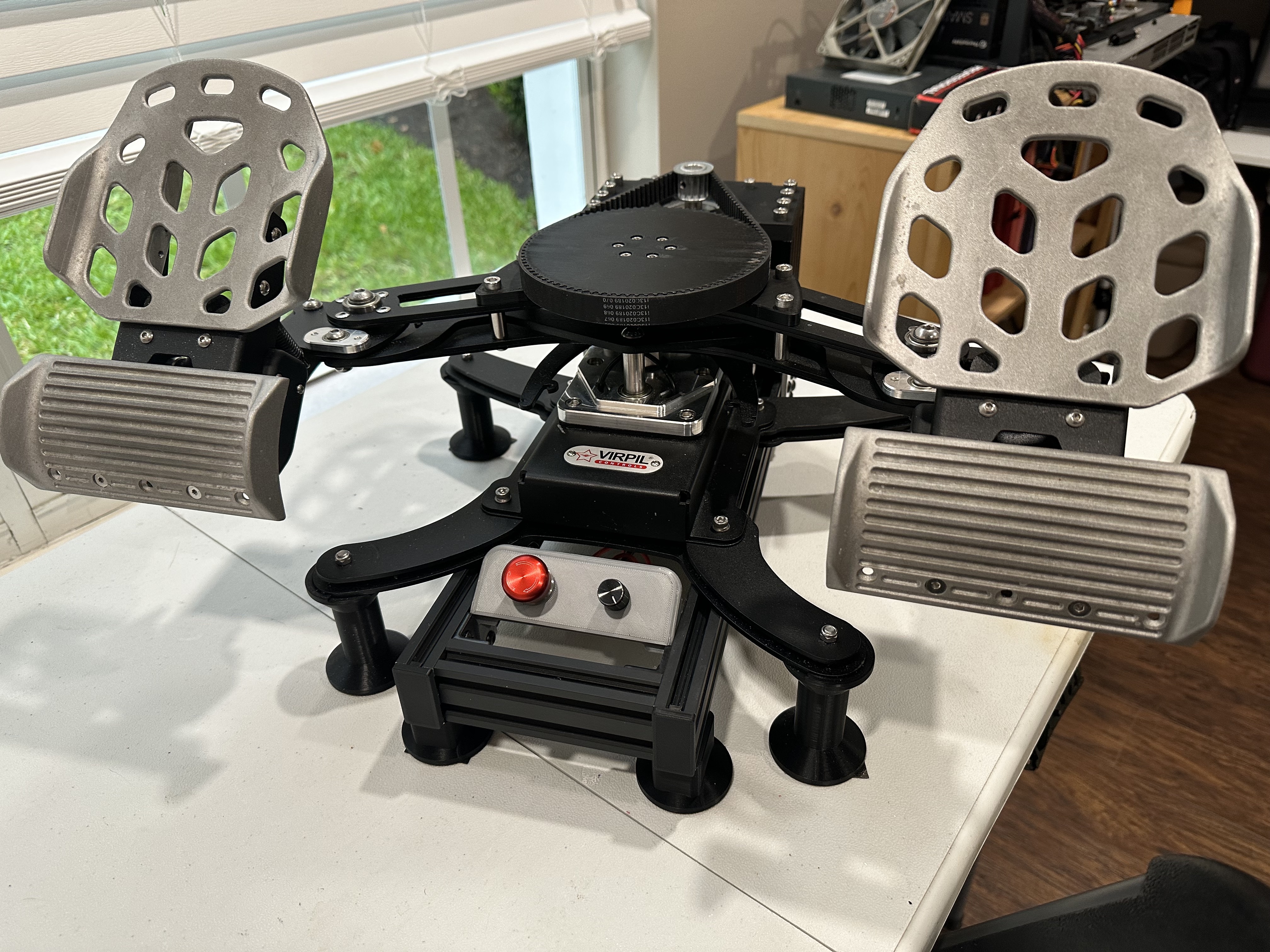
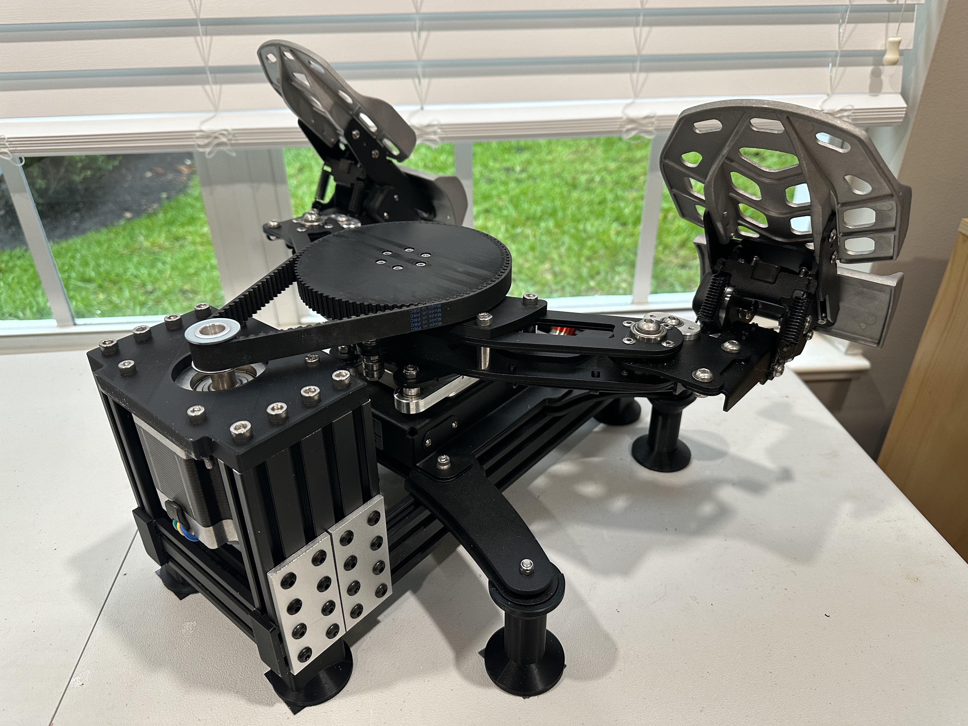
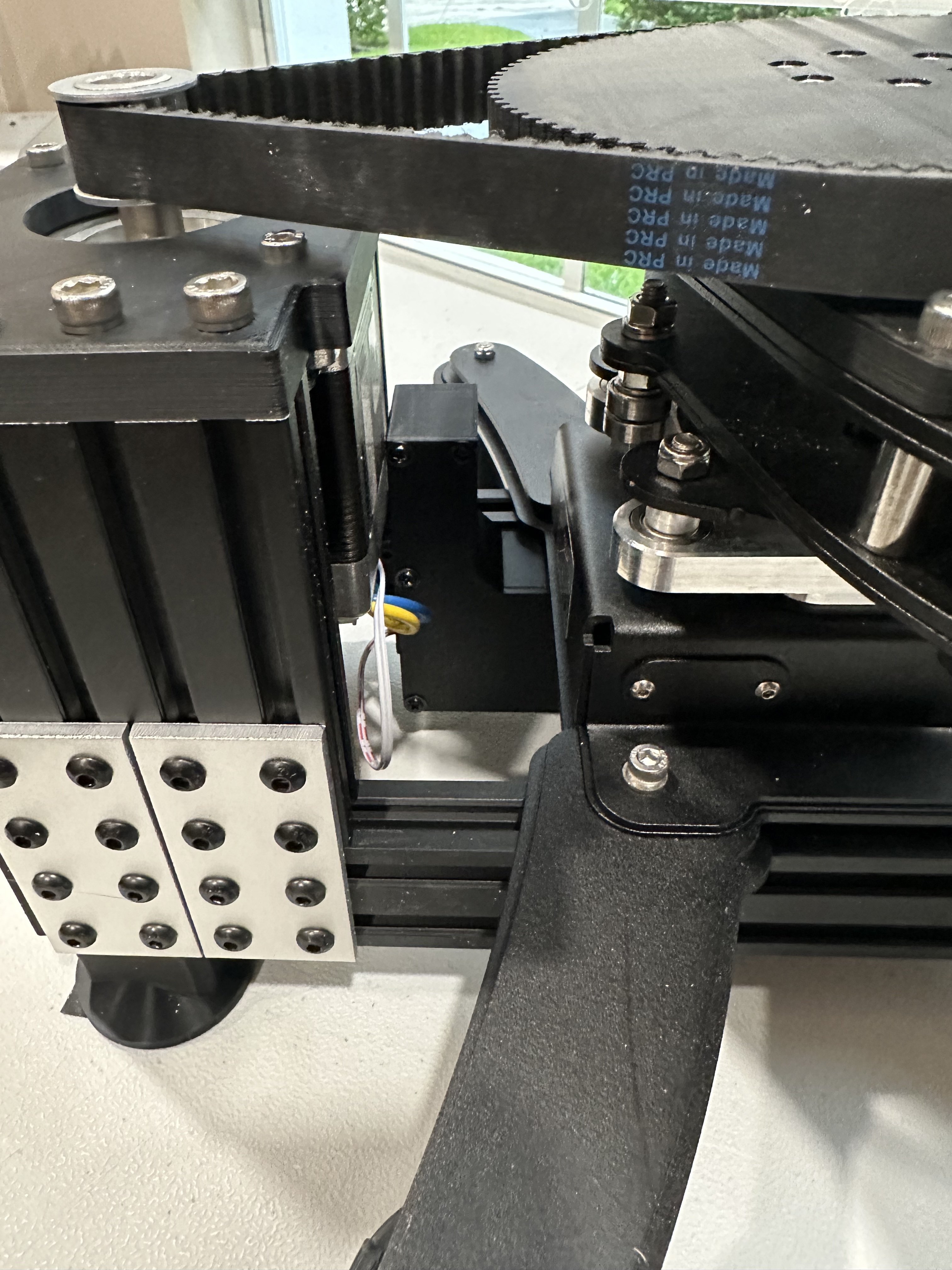
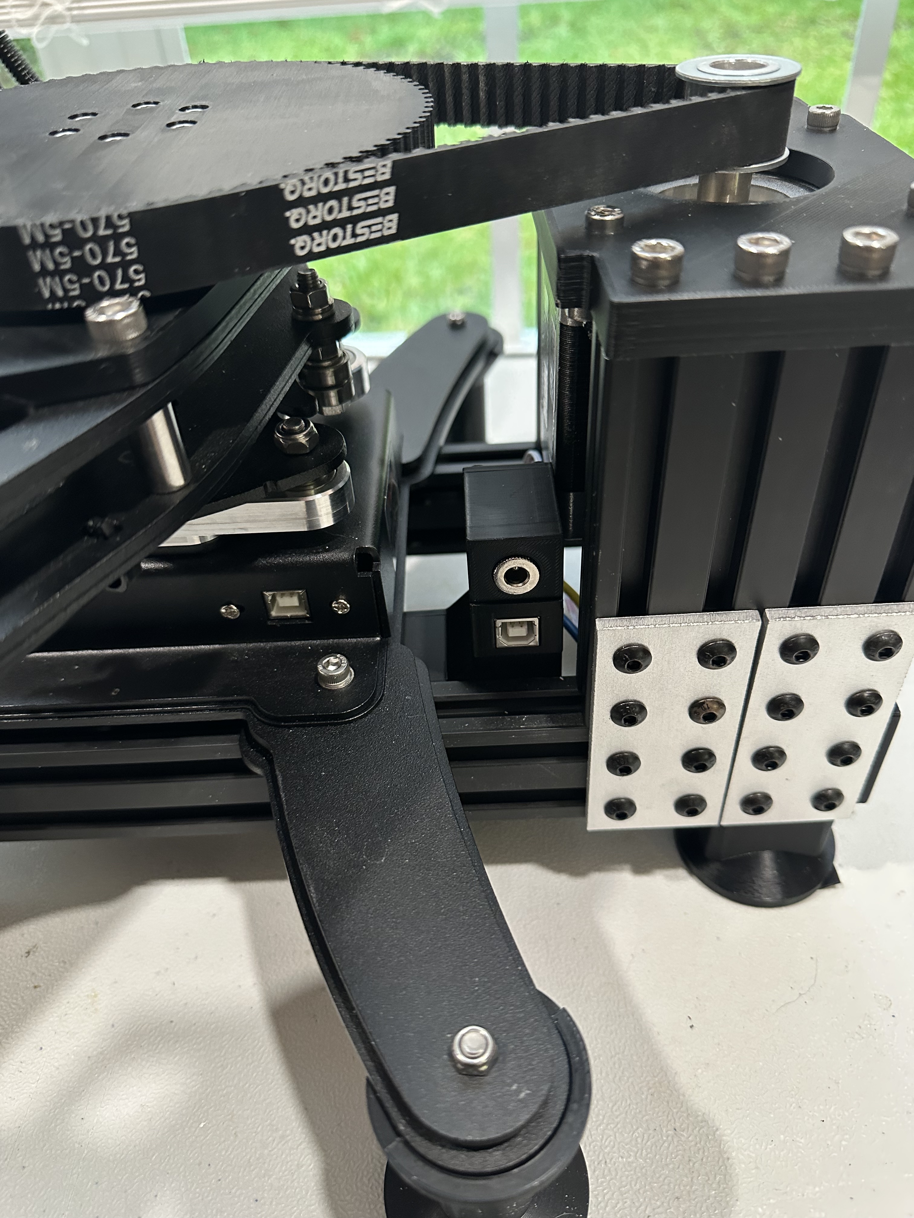
5.6 Gallery